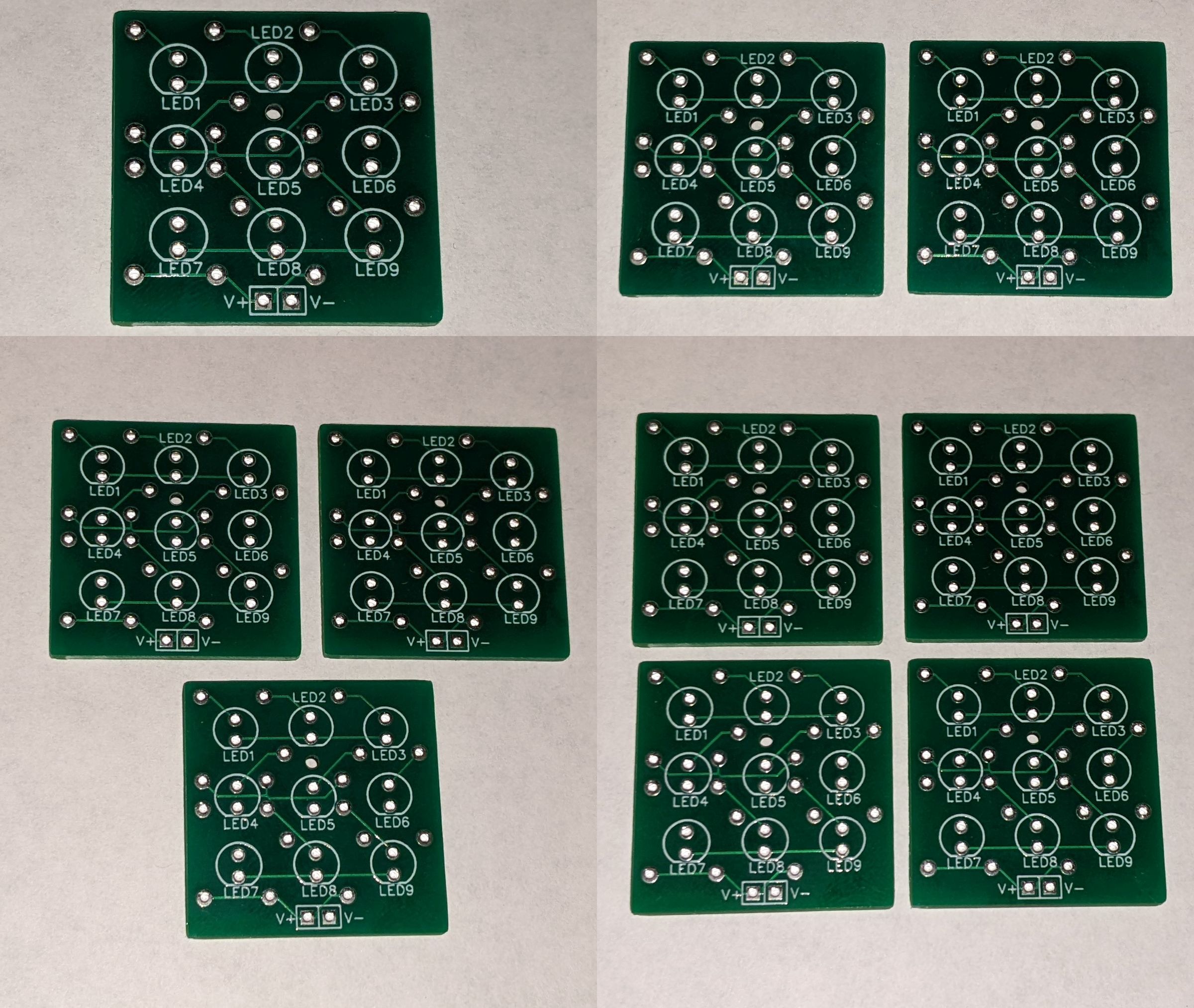
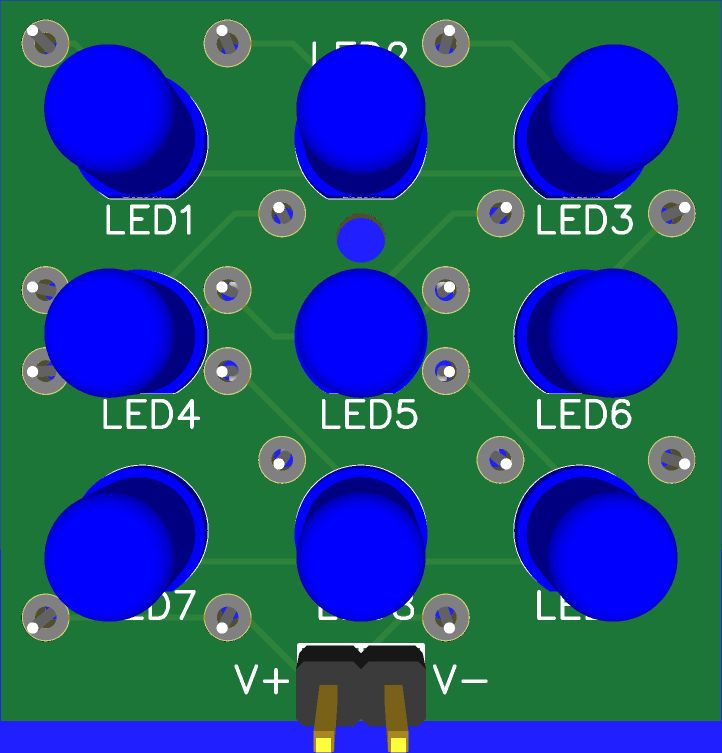
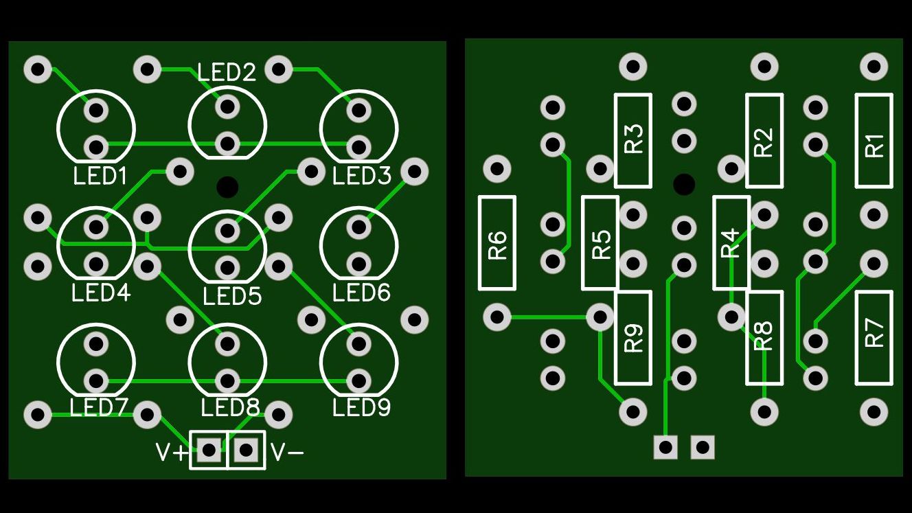
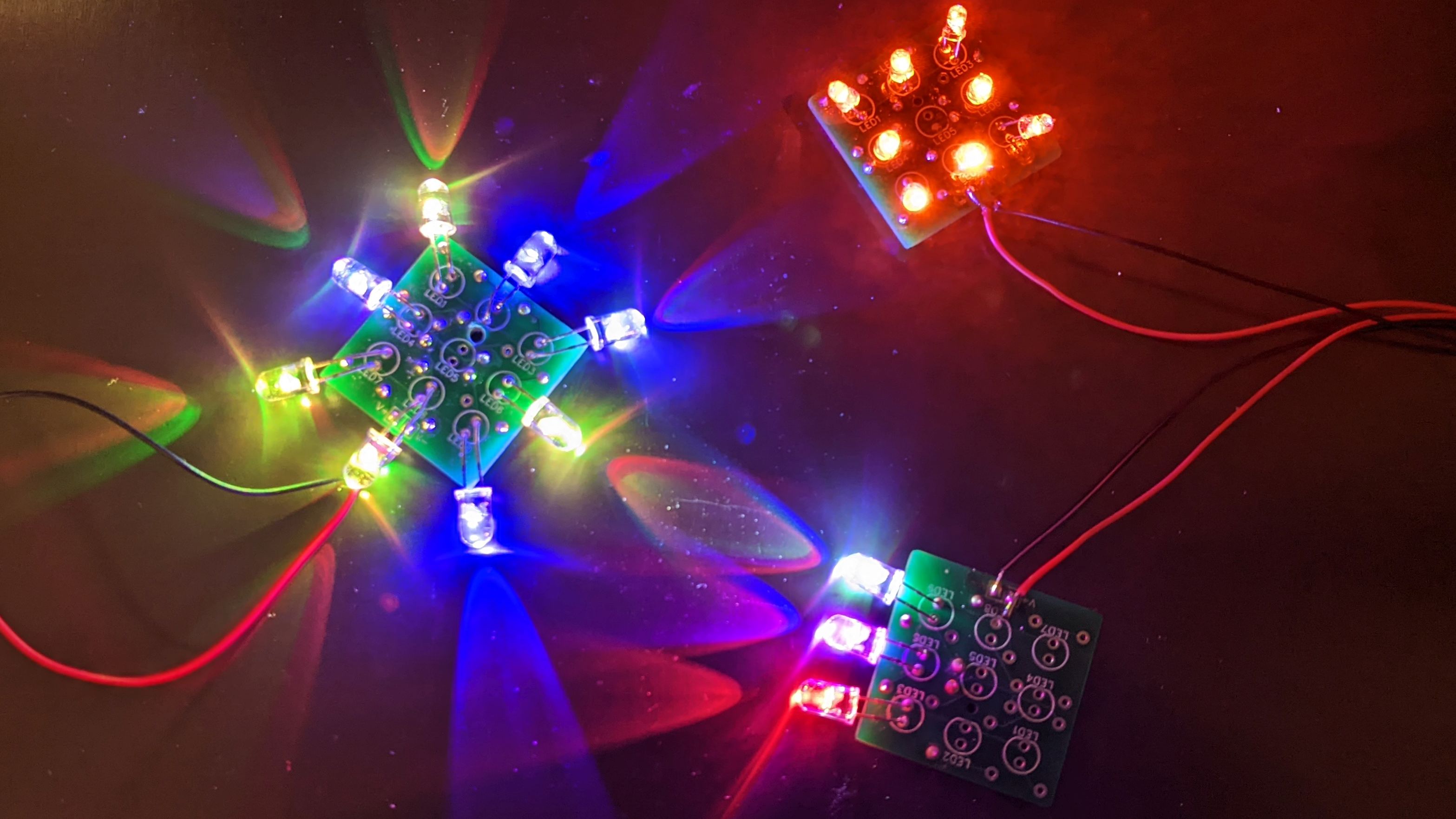
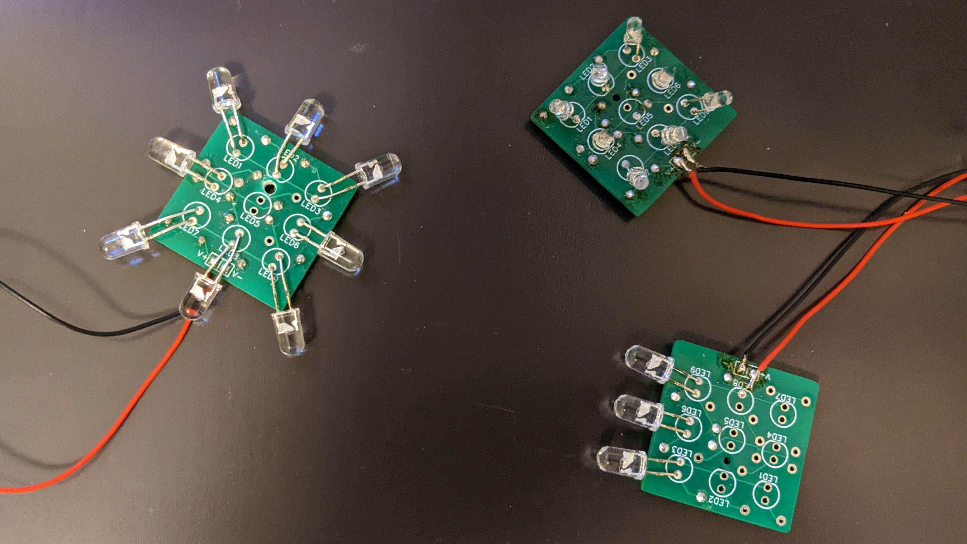
When you need a bit more light and a bit more control
Details
OPTIONS
ELECTRICAL SPECS
PHYSICAL SPECS
DESIGN
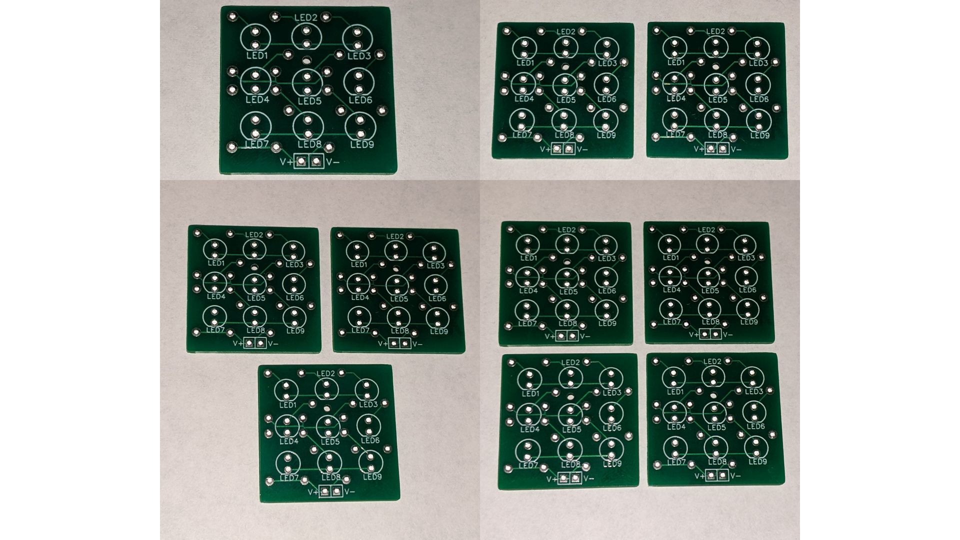
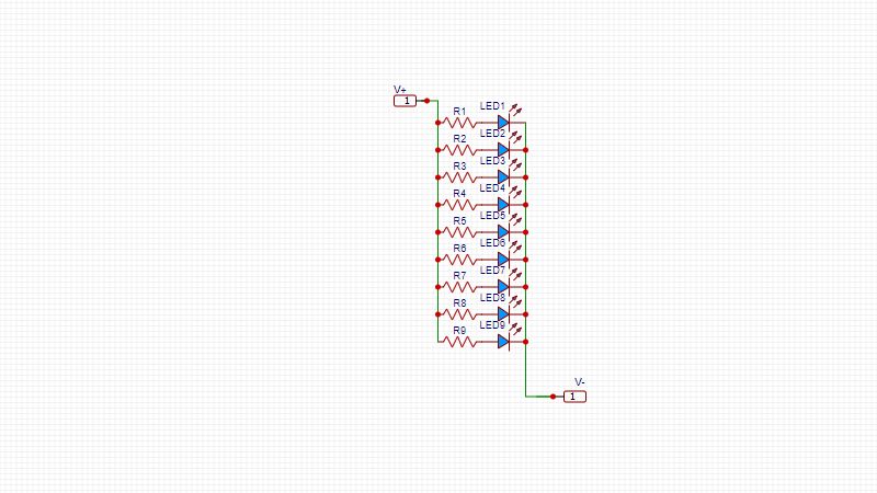
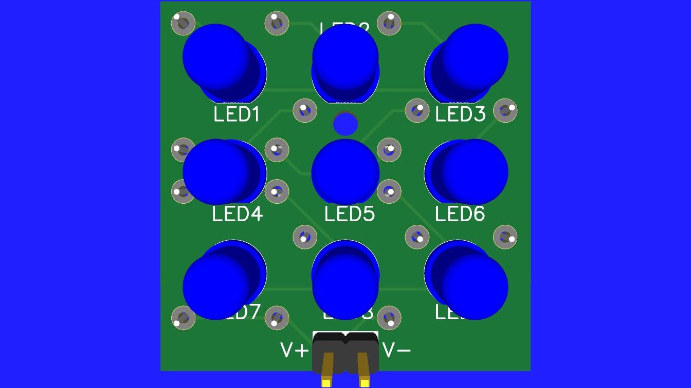
Design is really up to you.
Since each LED has it's own resistor, the resistor is chosen based on the source voltage, the voltage of the LED and the brightness you desire.
Most individual 5mm or 3mm LEDs can work with anywhere from 0 (off) to 20mA (Full Brightness), so select the brightness you want.
For most red, orange or yellow LEDs, they turn on at about 2 volts. Most others turn on at about 3 volts.
If, for example, you are powering this board with 3 AA alkaline batteries, you would have about 4.5 volts.
Resistor = (Supply voltage - LED voltage) / Brightness. For a Red LED at half power Resistor = (4.5 - 2)/ 10mA = 250 Ohms. Since that's not a popular value, maybe try 220 ohms. It's close but will be a bit brighter.
From there it's up to you how many LEDs, what type and how to lay them out.
The Full Display 3x3 board is available in single pieces with discounts for multiple pieces.
Electrical Specs
Schematic is above
Simply stated, there is one resistor for each LED and all are in parallel. This allows full control in that you can put any LED in any position and select resistors for each to control brightness.
The resistors are numbered the same as the LEDs. R1 is connected to LED1, R2 is connected to LED2 and so on.
Traces are limited to about 500mA.
Power connector at the bottom is 2.54mm pitch and wired in parallel for each resistor/LED pair.
Physical Specs
Layout is above
Board is 30mm x 30mm x 1.6mm
The footprints are for standard 1/4 watt resistors and 5mm LED (though 3mm could also be used).
Power connection is standard 2.54mm pitch. Positive and negative are both 2mm from bottom edge and centered horizontally.
The mounting hole is 1.5mm, centered horizontally and 10mm from top edge. In order to fit this small hole, LED2 is moved up slightly and LED5 is moved down slightly.