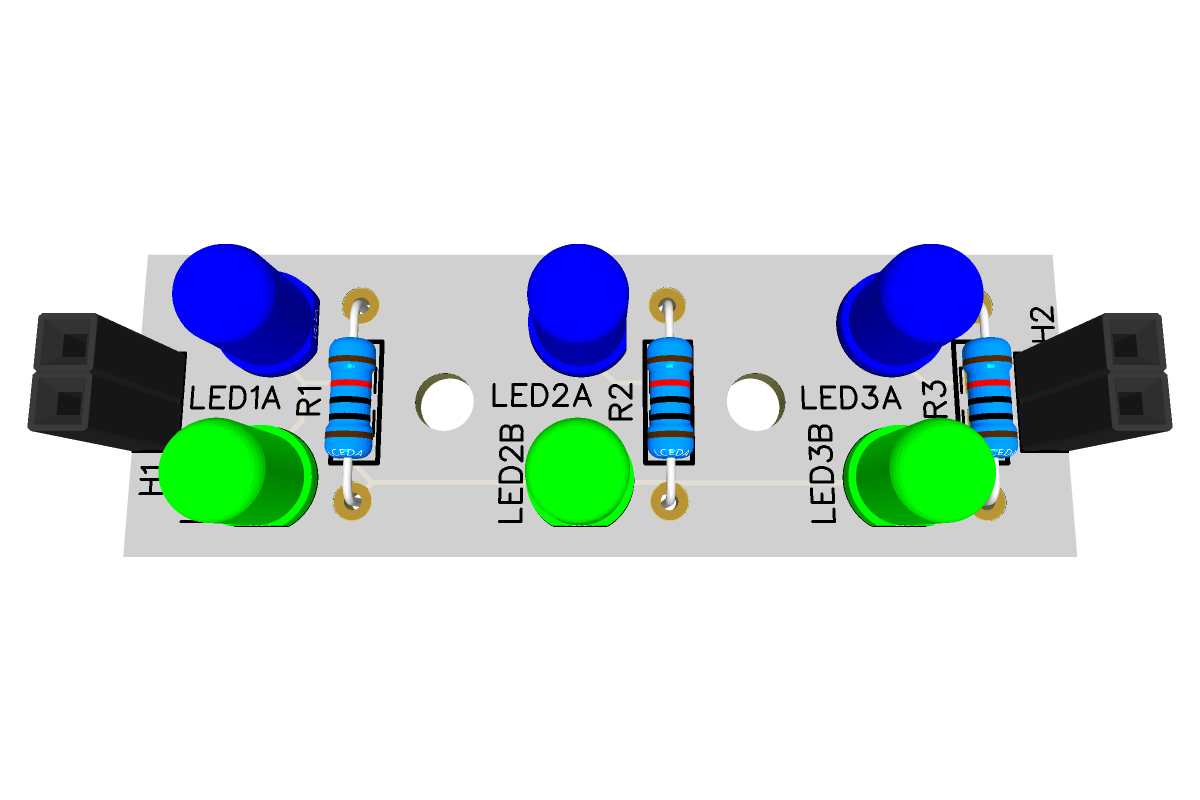
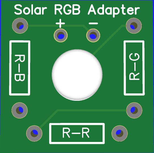
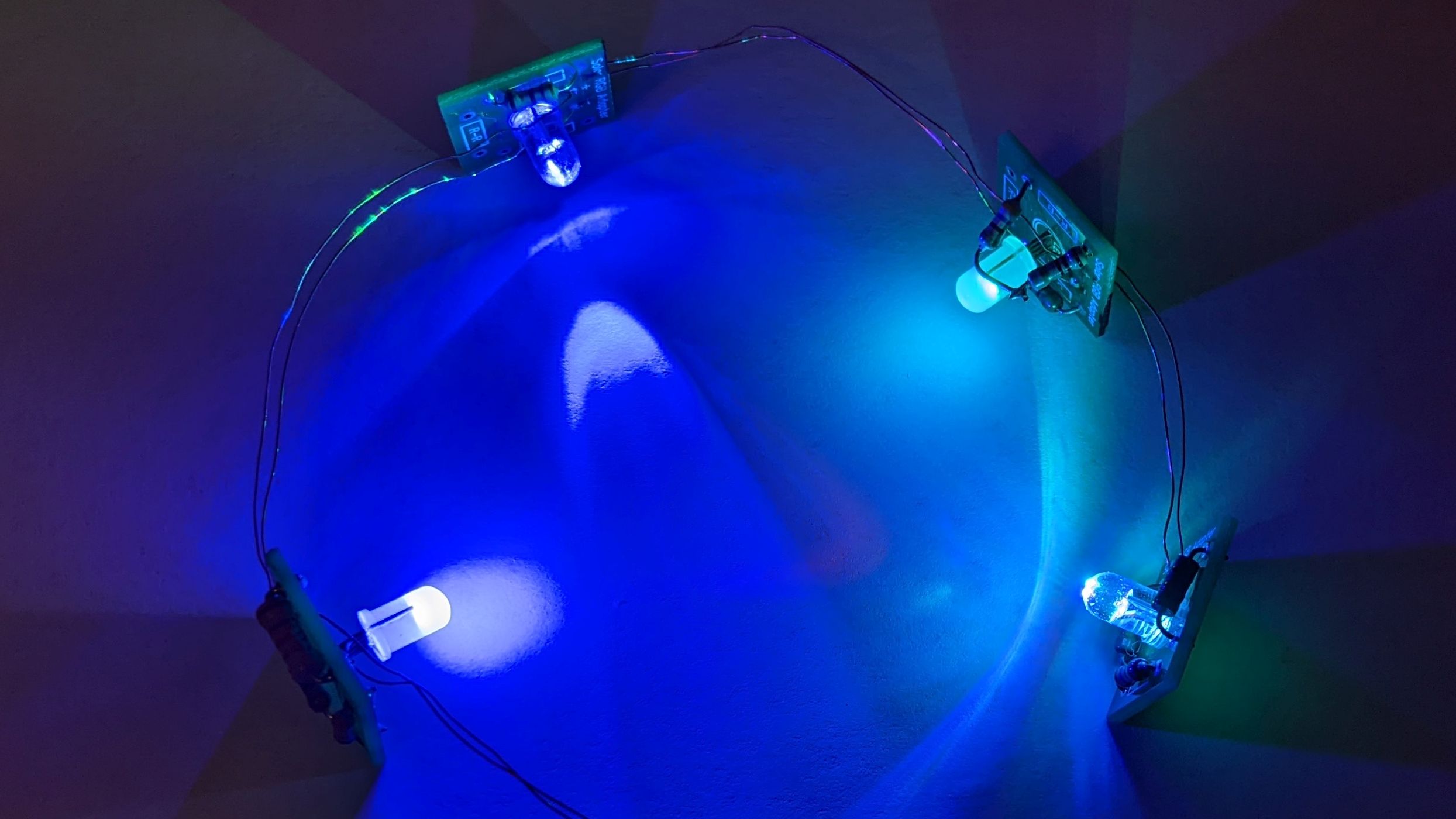
Rendered Product

RGB Adapter

Turn your 4 pin RGB LED into almost any color

Details

OPTIONS
Ordering Options
ELECTRICAL SPECS
Schematic
PHYSICAL SPECS
Layout

DESIGN

Example On
Example Off
Rendered Example
Schematic

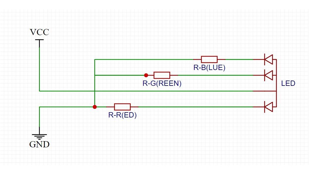
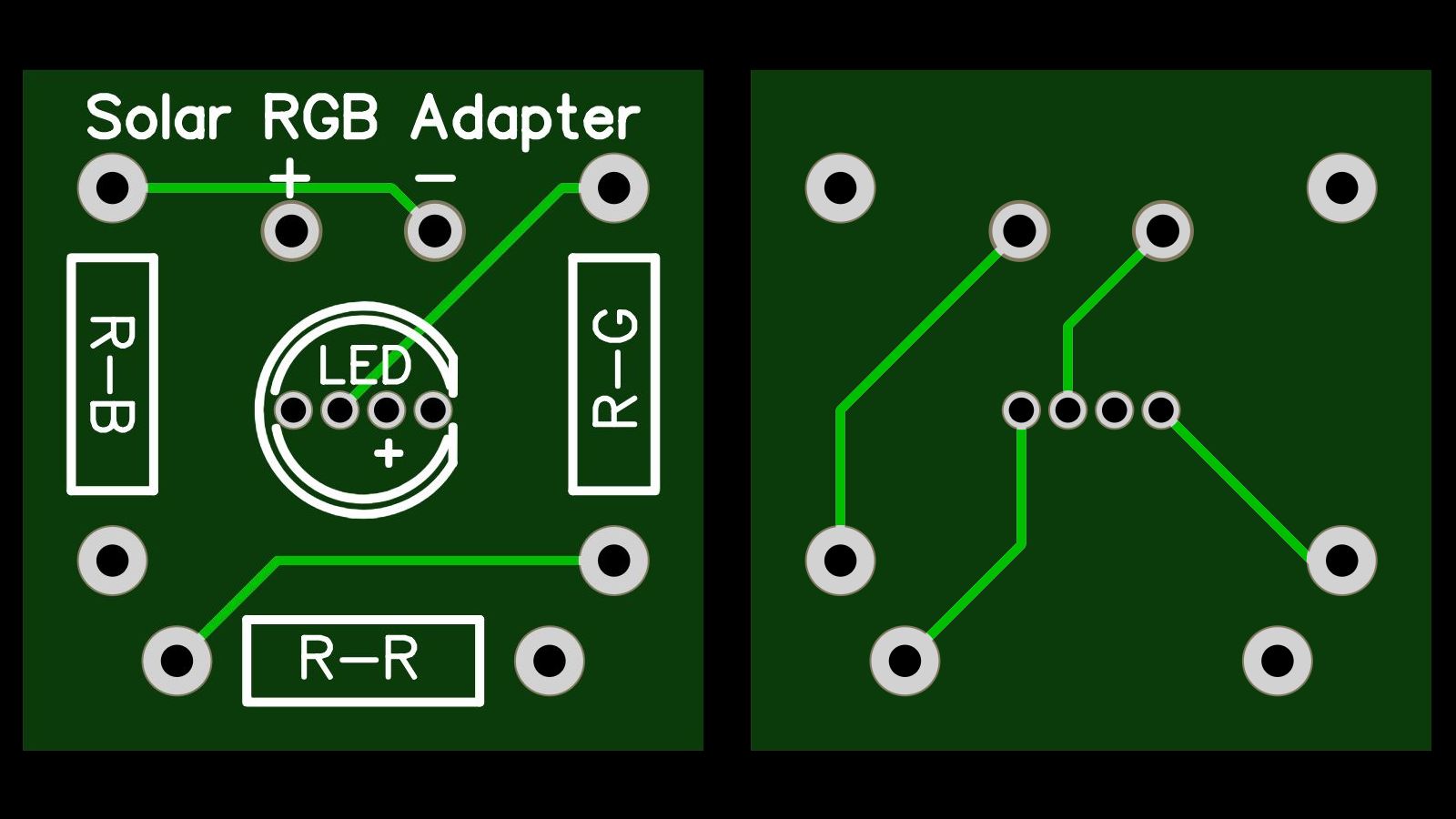
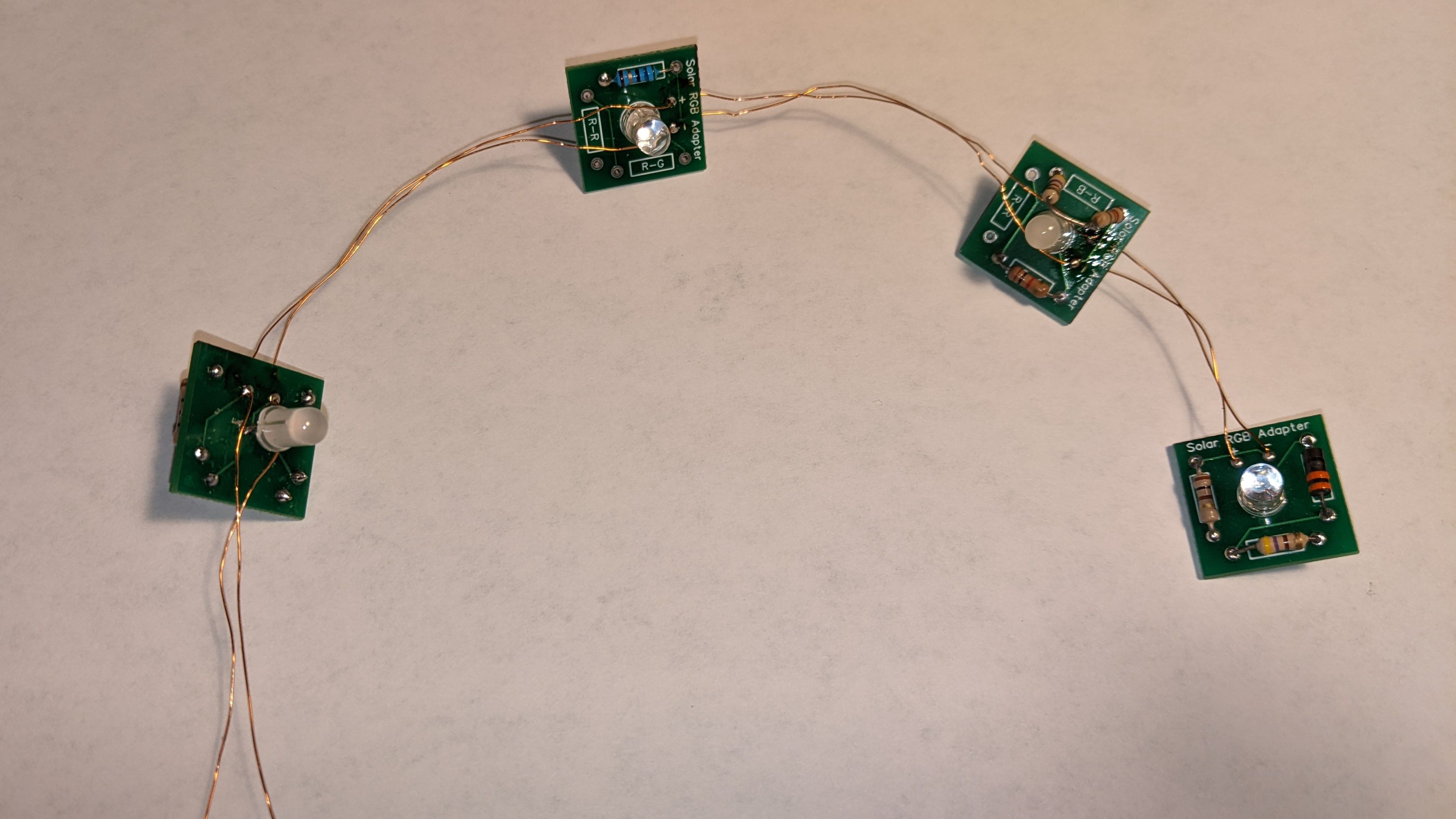
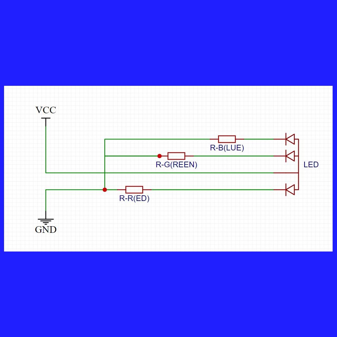
Design mostly comes down to which resistors to use.
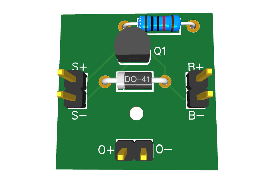
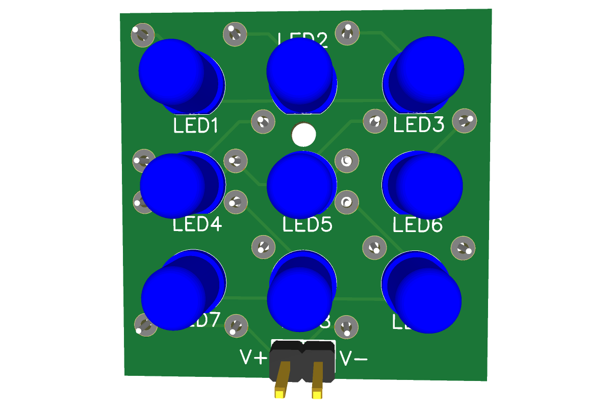
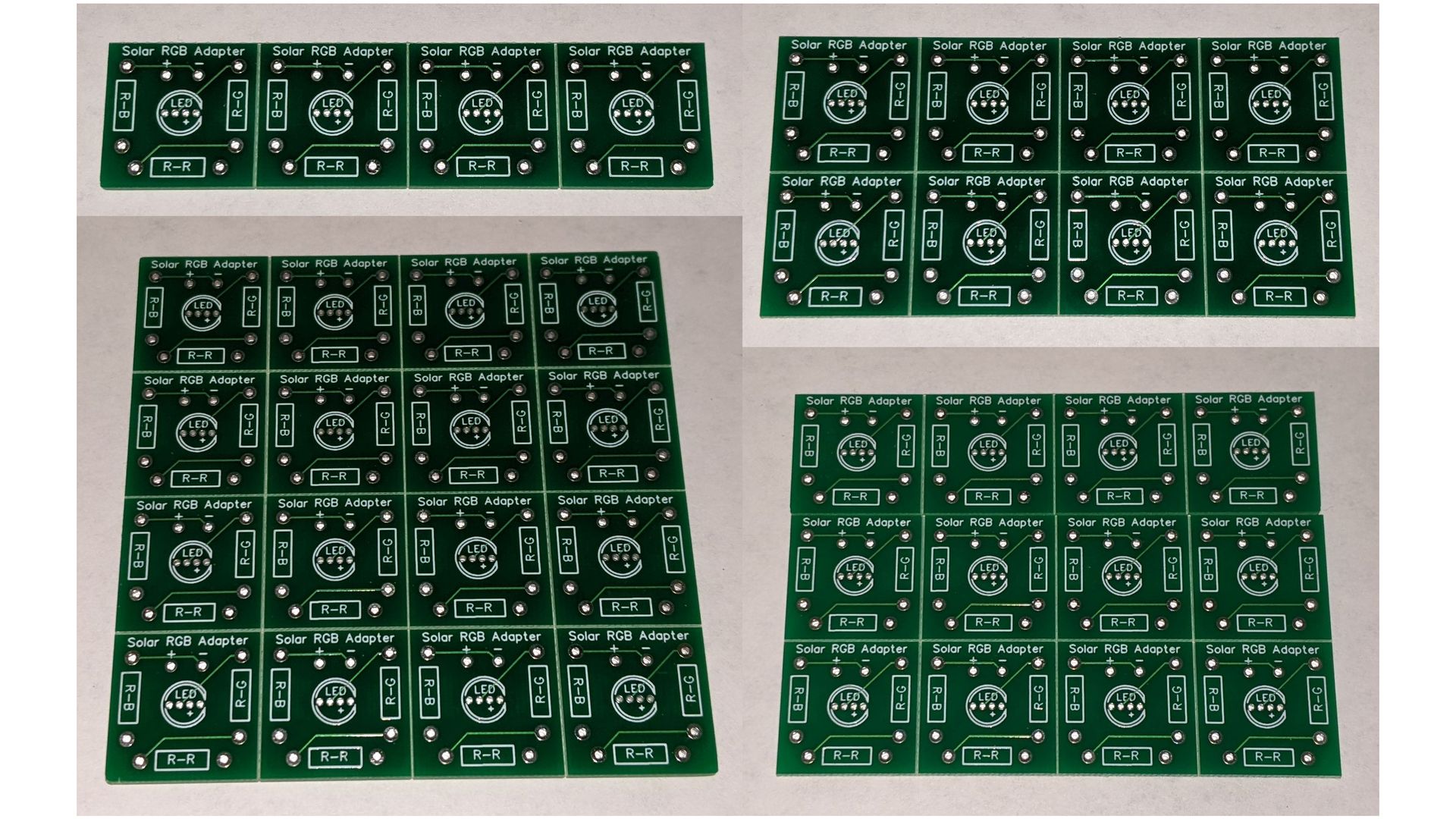
  1. Let's make a few assumptions: Power source is about 5 volts and the LEDs inside the package are about 3 volts for Green and Blue and 2 volts for Red. The package is "Common Anode", but see below for "Common Cathode"
  2. If you just wanted a full 20mA Blue LED, you could leave out the resistors for Red (R-R) and Green (R-G) and then the blue voltage drop would be 2 volts for about 20 mA. Resistor = Volts/Amps = 2/0.02 = 100 Ohms.
  3. For Cyan, we're leaving out the Red light component, so we could put another 100 ohm resistor for Green (R-G), but is that really Cyan or more of an Aqua. Also, if you increase both resistors, you won't necessarily get a dimmer version of the exact same shade.
  4. Ultimately, design for the exact color you want will require some experimentation and rather that soldering and desoldering multiple resistors, I recommend a breadboard to tune first and then record and apply your combination of resistors and apply power.
  5. As to the "Common Cathode" solution, really the only difference is that the common pin is the complimentary voltage, so just switch the polarity when you apply power and everything else should be equivalent.