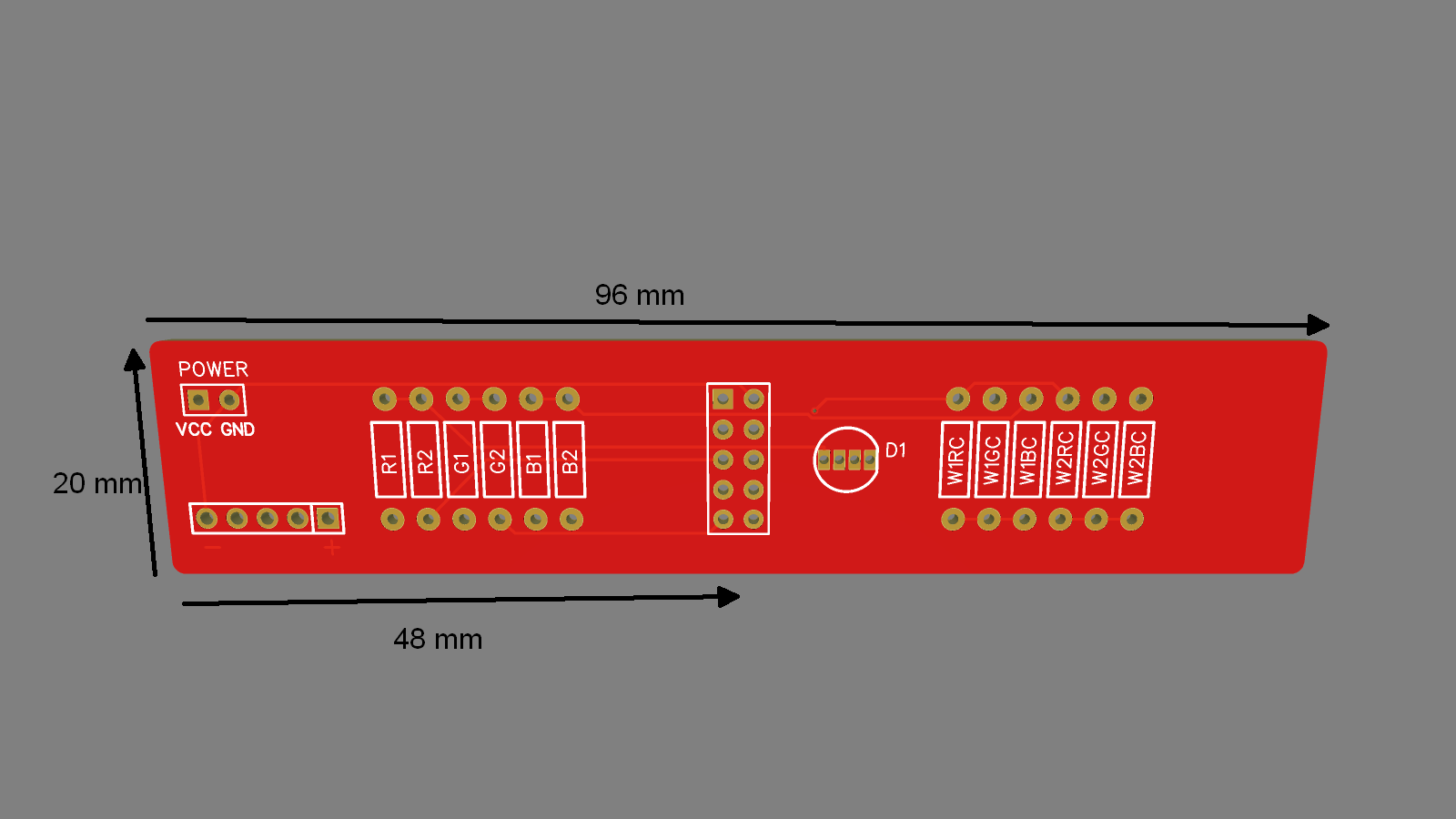
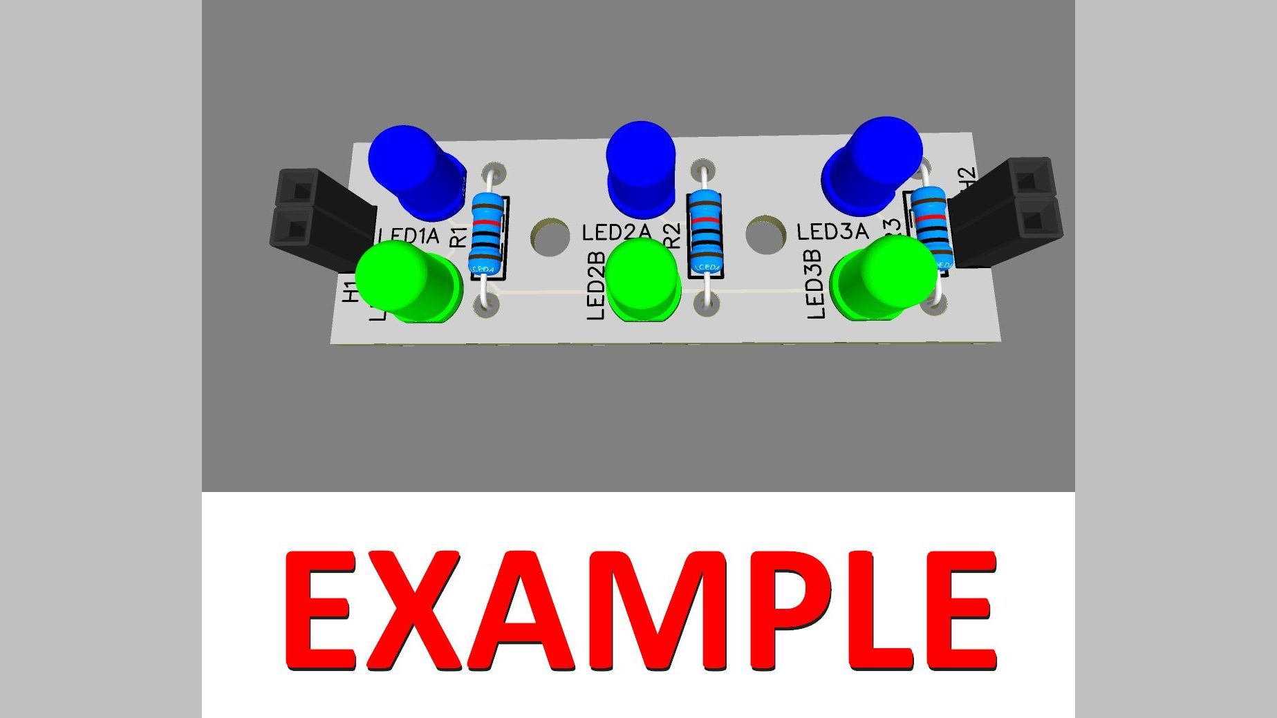
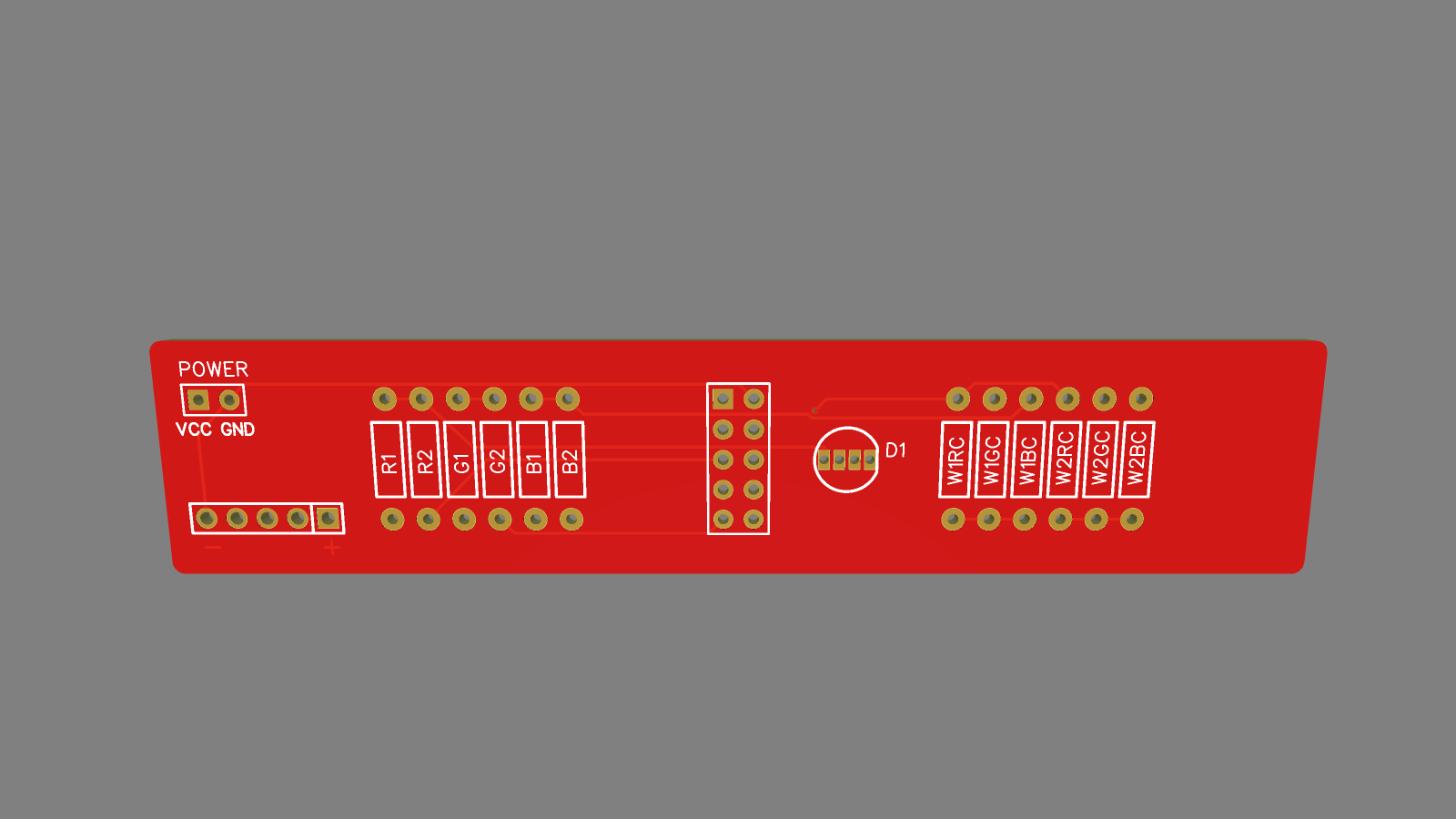
Rendered Module

Key Test Module

Malfunctioning keys are a pain

Details

Design Goals
(Click for List)
How It Works
(Click for Details)
File Downloads
(Click for List)

Build

We're just getting started with version 1.0 now, but this is where you will find links to purchase kits and assembled boards. Meanwhile if you want to support the project, check out the links in the "Support The Project" section below.

This page is for the Key Test Module. If you have a mulimeter you can test for continuity to validate every switch. This module should make it simpler in the long run if you are building more than one "Octave".

  • Install all resistors. I used 1K Ohm for all Red and Blue and 2K Ohm for all Greens. This yields reasonable individual colors and a rather harsh greenish white, but good enough for a tester. If someone wants to use this as a base for a color organ module, feel free.
  • Next add the LED. I used a common positive negative for the design. If you only have a common negative positive LED available, just switch the polarity of the power inputs.
  • Then add the header pins on the bottom side so they will mate with the header on the Switch Board
  • Finally add the power source. In a future version I will likely be moving the second 2 pin power connector to the other end of the board (or copying it) to make it easier to daisy-chain these test boards.