We're just getting started with version 1.0 now, but this is where you will find links to purchase kits and assembled boards. Meanwhile if you want to support the project, check out the links in the "Support The Project" section below.
This page is for the core of the system, the switches for the keys or "SwitchBoard". Depending on how big a keyboard you want to build, the parts list per octave follows.
Spacers (Assuming the standard bricklaying pattern, first level gets half spacers on ends with full spacers between, second level is all full spacers, third level repeats first. Also I used 3 small spacrs per black key to raise them up above white keys)
Keys (8 white keys per "Octave" and 8 reversable black keys per "Octave")*
Switches - I used 4.3 mm tall 6x6 mm tactile switchs for the white keys and 9.5 mm (just barely cleared) 6x6 mm tactile switches for the black keys.
Bolts - I used 2 each m3x10 bolts for each white key and 2 each m3x15 for the black keys
Headers - The main interface header is a 2x5 header with 2.54 mm pitch. You'll need two per octave and two more per octave for any module connected directly to the switchboard
* Each switchboard is actually 8 keys, whereas a full octave has 14 possible keys**. That means one extra white and one extra black per octave here.
** This system was designed to allow multiple configurations whether you start with "A" or "C" or some other natural key.
At that point, assuming you've tested for functionality with the light test module, you've gotten as far as I have. Time to start developing sound generation modules.
Support The Project
There are a few ways to support me and my efforts towards the project while we build a following. I've invested my own money thus far, so anything you can contribute would help.
If you have the skills to add to the project, that would be primary.
Spread the word. I only have so much of a social media presence, so the more word of mouth we can get the better chance of finding people to add to the project.
Check out and consider subscribing to my YouTube channel. That is where I post all videos for this project and lots of other stuff. In case you didn't know, YouTube changed the rules and set a larger minimum number of subscribers before I can get monetization back. Getting closer, but every sub helps.
I have some circuit boards and kits that you might enjoy using or building. You can find them listed here in my store, but they are ultimately sold on eBay for your security.
The initial design will be based on switches. While I realize this does not allow for "Velocity", the point is to get a functioning keyboard.
That said, I do have thoughts on how to add a variable voltage to each key and as such, all other designs must keep that in mind.
The board itself is designed to be small enough to be prototyped at prototype rates while maximizing the number of "keys".
Beyond that, I have tested a thinner (1mm) FR4 material for flex and have ordered keys made that way.
Also, as with all parts in this design, we should consider safety for the end user and as such this board has all sharp corners removed by adding a curve. For this version, I'm using a 1.2mm radius. I'm thinking it will be small enough to keep real estate on the board while removing the sharp corners.
The board itself is a standard 1.6mm thick and uses 6x6mm through hole tactile switches. The heights will vary depending on how many spacers we add so the white vs black keys are at different heights.
How It Works
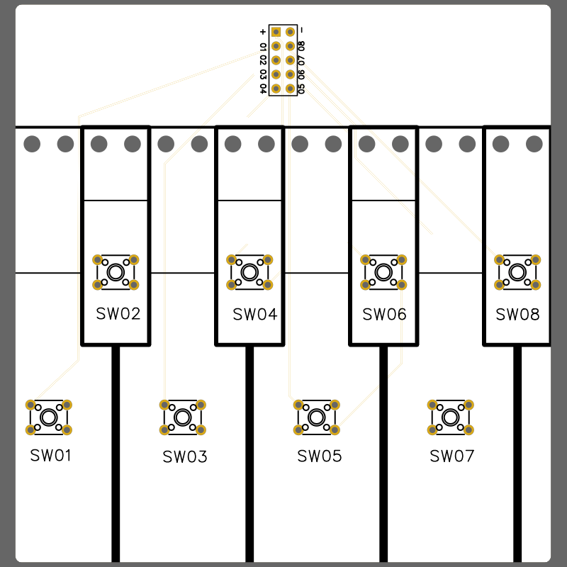
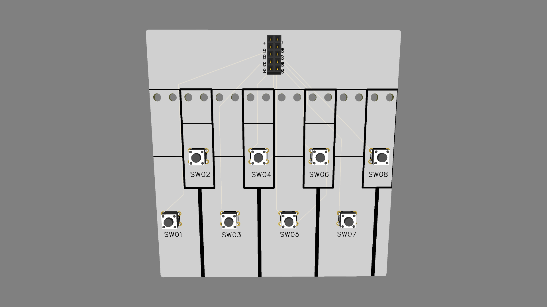
The board is designed to be small enough to be prototyped at prototype rates while maximizing the number of "keys". It was also double sided so by alternating sides we get a full octave. However, after some experimenting and a failed first surface mount prototype with 7 keys per side, I realized 8 keys per side would be needed for a single sided through hole design. That does however, leave us with two extra keys per pair of boards.
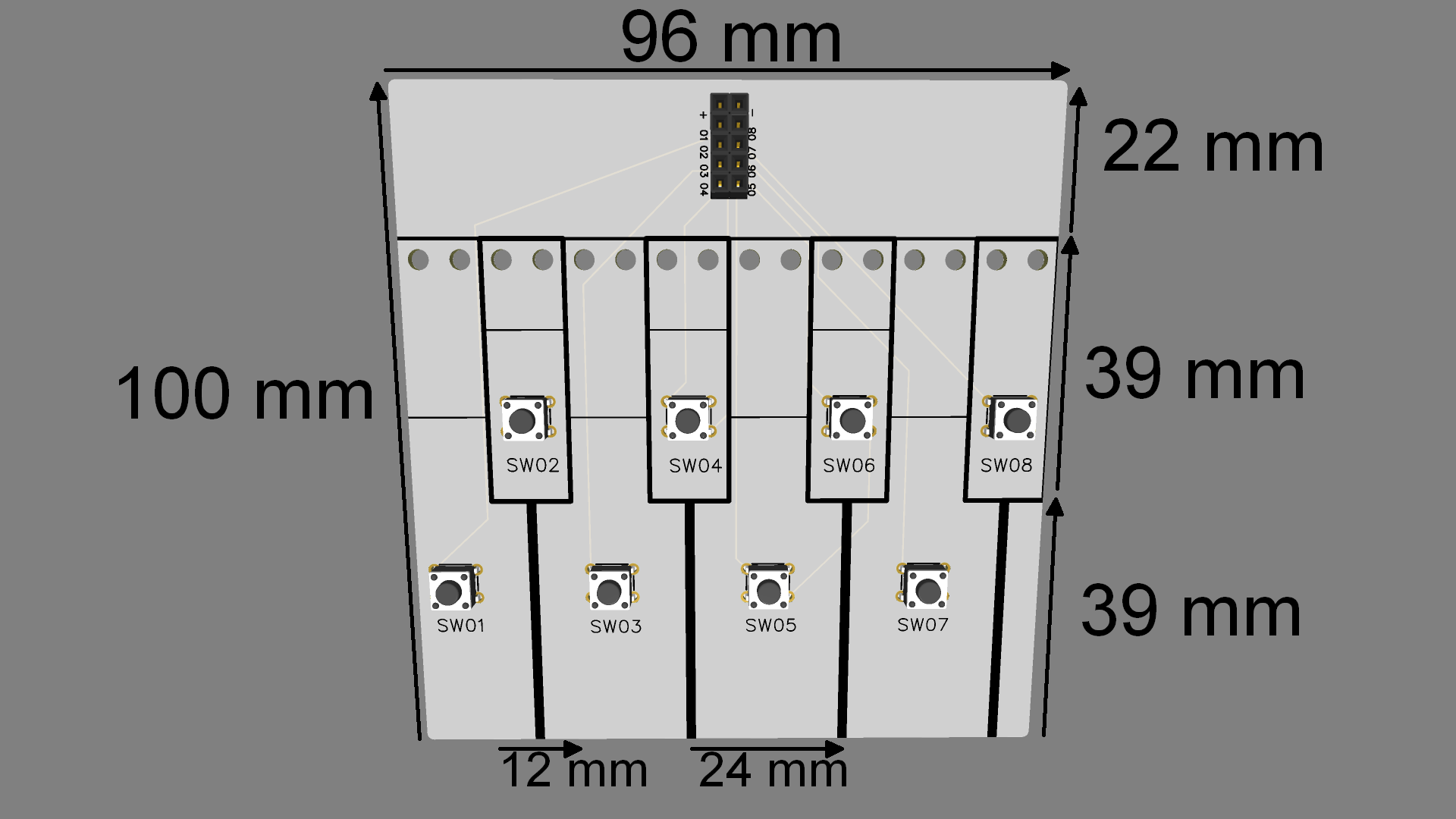
After measuring actual piano keys, I settled on a compromise that makes the white keys just a bit smaller while making the black keys perhaps just a bit bigger but maintaining something close to real width while also making the black and white keys a consistant size (12mm).
The length of the keys was also compromised to fit the prototype sizing while also allowing some space at the back for connections to other modules. 13mm became a key number as the black keys are 39mm and set back 39mm from the front making the white keys 78mm and leaving just over 20 mmm for connections.
For the interface, I originally had a single row header with 10 pins. The first two were power, though you only really need one power rail for the switches. After that was an unconnected pin and then the connections to the 7 switches.
In the redesign I decided to switch from surface mount to through hole for two reasons. One, the switches would be more mechanically secure and Two, surface mount is more difficult for novices.
Also in the redesign I realized that a double row header would be better for a few reasons. One, more mechanically stable. Two, if someone wants to make a module that spans two half-octave PCBs and still keep the design to 100mm width, the header would need to be rotated. Three, even for a half-octave plug in module it takes less real estate from larger components, at least, that's what it feels like to me.
That leads us to the 2x5 header with 2.54mm pitch. With the board being 96mm wide that does make it very tight for full octave modules, but that's where I am in the design process right now. The header itself is configured so that the power pins are on the top two pins with switches 1 to 4 on the left and 5 to 8 on the right.
From there we have to consider the heights of the switches. Switches for black keys should be taller than for white keys. Before we can determine switch heights though, we have to consider how we are going to raise the key tops themselves. For that I designed spacers. There is another section on spacers, but the upshot is that these are all (for now) 1.6mm thick.
Here's where I am now. I have ordered multiple circuit boards and since the lowest profile switch is 4.3mm, I think I can get away with 3 layers of 1.6 mm spacers for 4.8 mm or 0.5 mm clearance. If I'm wrong, there are smaller spacers I can use to raise them higher. The problem is I won't really know until all the parts arrive.
As I said, I've ordered a variety pack of switches with differing heights. The plan is to build up for the white keys and see how the clearance works with the flex of the white key pcbs. From there I'll try to determine the necessary height for the black keys and appropriate switches.
Stay tuned and I'll update progress here and on my YouTube channel (links in the downloads section)
File Downloads
Go to your preferred board manufacturer like JLCPCB or PCBWay or whatever works for you.
When you see the opportunity to upload a Gerber file, upload the file you can download below
In many cases you can select from multiple colors of "Solder Mask". This board in this project is currently White, but it really is up to you.
If you have a choice, the thickness of the board is 1.6 mm, but for this board that is NOT critical.
You will also need 8 6x6 mm through hole momentary tactile switches. Height is to be determined, but if you want to follow along, just get a box of assorted heights.
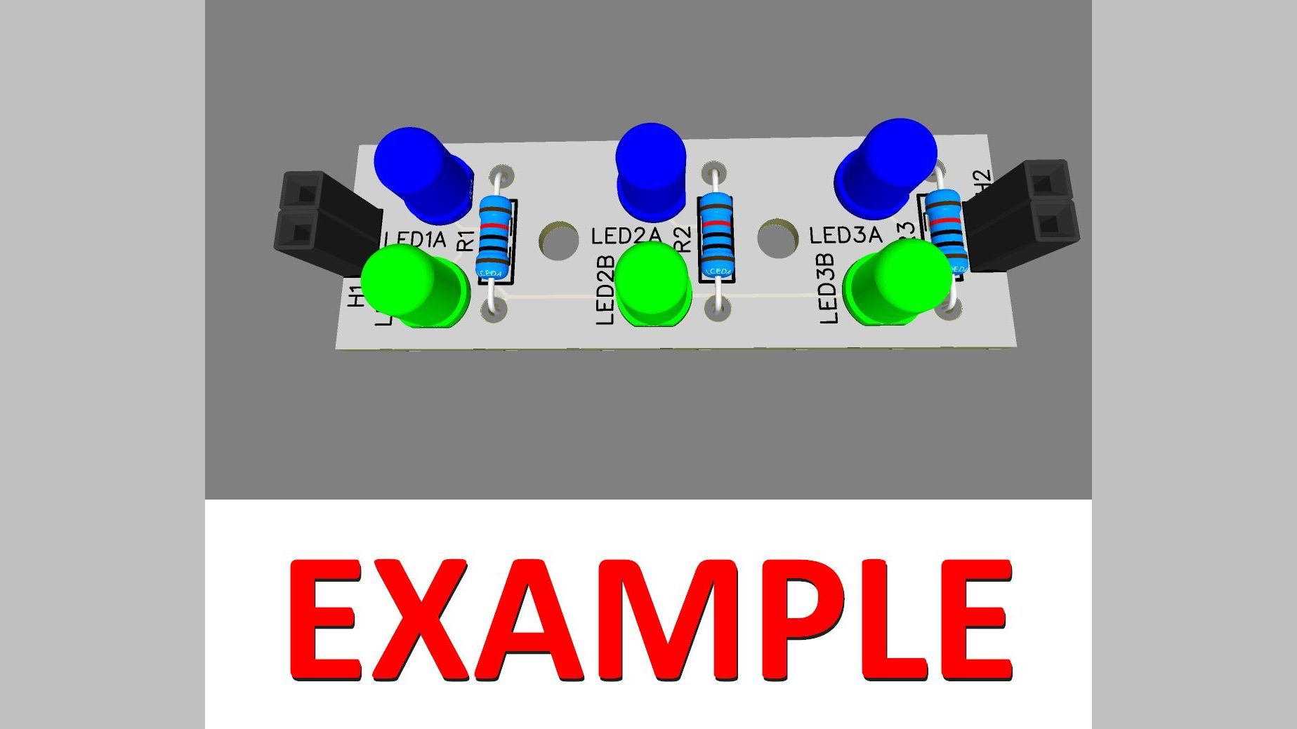
Finally you will need to connect to the header. Either with a 5x2 header with 2.54 mm pitch or by soldering directly to the board. This will also require some sort of power source and a way to verify the signals are being switched. For that, the very first module, a light based test was developed. More on that in the modules section.